

Evaluation Method of Internal Resistance for Repurposing Using Middle and Large-Sized Batteries
by
 , , and
Min-Gyu Lim
1,2,
Jae-Beom Jung
1,2,
Nam-Hyun Kim
2,
Ji-Myung Kim
1 ,
,
Jian Shen
1 and
Dae-Seok Rho
1,* 1
Department of Electrical Engineering, Korea University of Technology & Education (KUT), Cheonan-si 31253, Chungcheongnamdo, Republic of Korea
2
Korea Testing Laboratory, 112 Jiksanro, Seobukgu, Cheonan-si 31253, Chungcheongnamdo, Republic of Korea
*
Author to whom correspondence should be addressed.
Energies 2023, 16(15), 5652; https://doi.org/10.3390/en16155652
Submission received: 13 June 2023
/
Revised: 25 July 2023
/
Accepted: 25 July 2023
/
Published: 27 July 2023
(This article belongs to the Section A1: Smart Grids and Microgrids)
Abstract
:The number of used batteries is expected to dramatically increase in the near future due to the expansion of the electric vehicle (EV) market globally. Accordingly, the Korean government has improved the supporting structures for the recycling system for used batteries, and in particular, in the field of repurposing, various studies are being conducted with a focus on effective evaluation methods that can secure the performance and safety of batteries after use. The repurposing of used batteries is mostly adapted in the field of energy storage systems for normally used EV batteries and a total inspection before repurposing is required due to battery characteristics that can vary depending on the operational environments of and accidents involving medium- and large-sized batteries for EVs and energy storage systems (ESSs) that have been occurring continuously for the past few years. Therefore, this paper investigates the operating mechanisms of the internal resistance test method and implements a test device for middle- and large-sized cells and packs. Based on the proposed test method, the internal resistance of nickel manganese cobalt (NMC)-type commercial large batteries is analyzed according to the SOC (state of charge), SOH (state of health), ambient temperature, and connection degradation of batteries. The distribution degrees of the alternative current (AC) internal resistance (IR) and direct current (DC) internal resistance (IR) measurement methods under state of health (SOH) test conditions are about 7% and 50%. It was found that the DC IR measurement method is more effective in diagnosing battery cell degradation. The distribution degree of DC IR measurements for the degraded connection condition shows an increase of less than 1% regardless of the state of charge (SOC), while the distribution degree of the AC IR measurements shows an increase of up to 319%, indicating that the AC IR method is more effective than the DC IR method in identifying connection degradation. It is confirmed that the proposed method is effective in internal resistance measurement and safety evaluations for the repurposing of batteries.
1. Introduction
An enormous number of used batteries from EVs are expected to be produced along with the rapid expansion of the EV market throughout the world, while various studies have been presented in order to achieve carbon neutralization due to the strengthening of environmental regulations and awareness of customers. The global sales of EVs are expected to grow from 6 million units in 2020 to 26 million units by 2030, which is 27% of all car sales. Sales in South Korea by 2030 are estimated to be 3 million units based on the “National Roadmap for 2030” according to the cumulative base, compared to around 93,000 units in 2020. As a result, the market of used EV batteries is also expected to significantly increase [1,2,3]. On the other hand, since used batteries require full inspections due to the degradation characteristics, which vary depending on the operation environment and conditions, numerous studies on saving the time cost for the inspections have been carried out [4]. In order to repurpose the used batteries in a safe and reliable manner, non-destructive inspection methods are being adopted rather than destructive inspection and test methods, such as capacity, open circuit voltage, insulation, internal resistance, self-discharge, etc. In particular, it is important to evaluate the degradation characteristics of used EV batteries, which affect the performance and safety, in a rapid inspection by performing measurements of the internal resistance of the batteries. Studies have been conducted on battery cells using electrochemical impedance spectroscopy (EIS) to evaluate the internal resistance of batteries depending on the operation conditions for temperature and SOC [5]. However, there are no studies that confirm the safety and reliability of battery modules and packs based on the measurement and analysis of resistance by AC IR and DC IR methods for used battery inspection. Therefore, this paper presents a measurement mechanism of AC IR and DC IR based on the following international standards: international electrotechnical commission (IEC) 61960-3, IEC 62620, international organization for standardization (ISO) 12405-4, and underwriters laboratories (UL) 1974 [6,7,8,9]. The mechanism of AC IR measurement calculates the internal resistance based on the voltage measured at the battery terminals by inputting AC with 1 kHz frequency to the battery. The mechanism of DC IR measurement calculates the internal resistance based on the voltage variation by inputting DC for a constant time interval. Furthermore, in order to evaluate the internal resistance of a battery based on the abovementioned mechanisms, this paper implements a test device for the measurement of battery cells, which is composed of an AC and DC power source section, a sensing section, and a lithium-ion battery cell. Another test device is also implemented for the measurement of battery packs, which consists of an AC and DC power source section, a sensing section, and a lithium-ion battery pack containing cells, fuses, relays, and a battery management system (BMS). As a result of the evaluation of the internal resistance of the battery cells and pack according to various scenarios based on the proposed mechanisms and test devices, it is confirmed that the DC IR measurement is more effective in measuring resistance characteristics by the SOH than the AC IR measurement, while the AC IR measurement is more effective in evaluating characteristics of internal resistance due to the degradation of connections in the battery than the DC IR measurement.
This paper deals with the advancement of used battery performance inspection research by using commercial NMC-type batteries to study pack-level AC IR and proposes an evaluation method considering environmental parameters of the battery such as SOC, degradation rate, operating temperature, and torque of the electrical connection. There are not enough data on used batteries worldwide and it is difficult to establish standards for evaluating the used batteries. Therefore, this paper is expected to contribute to the evaluation of battery safety in the field of used batteries, as the number of used batteries will increase in the future.
2. Characteristics of Internal Resistance for Used Lithium-Ion Batteries
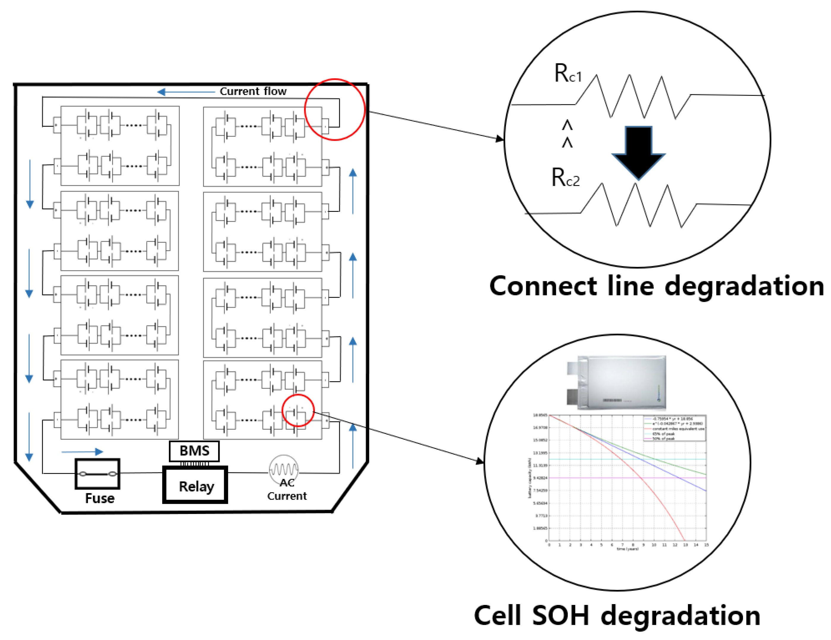
The internal resistance of a battery is commonly used as a key indicator of the battery’s characteristics [10]. In general, the internal resistance of a battery increases along with the degradation, and then the performance of the battery can be negatively influenced due to the energy loss caused by Joule heat and the discharge termination voltage drop. Also, since the internal resistance of a battery may be changed due to problems in the manufacturing process, it is common to consider the internal resistance as a key evaluation factor in most battery manufacturing processes. The evaluation criteria for internal resistance are adapted according to IEC 61960-3 for small batteries, IEC 62620 for industrial batteries, and manufacturer’s standards. In the standards, acceptance criteria of the internal resistance of the cell shall not be greater than the value of internal resistance, declared by the manufacturer [6,7,8,9]. The AC IR and DC IR will vary depending on the model as well as the battery type, and it is common for the manufacturer to specify a criteria value for pass or fail judgment. The standard for used batteries such as IEC 63330 [11] is being established, UL1974 is established and being applied, and a new Korea certification (KC) standard is expected to be published in October 2023 based on the temporary safety standard, all including the internal resistance evaluation in the abovementioned international and domestic standards. Additionally, the internal resistance of a used battery is measured, as shown in Figure 1, to evaluate the degradation characteristics of a battery based on the above standards. Battery degradation can be classified into two major categories: cell degradation and connection degradation. Cell degradation is caused by internal chemical changes resulting from the reaction of lithium ions in the cell, and such degradation can be accelerated by abnormal ambient temperatures or high currents [12,13,14]. In detail, various aging factors such as SEI growth on the negative electrode and cracking of the active material on the electrode influence the degradation over a period of use.
Connection degradation can occur due to physical factors such as continuous vibration or shock, and the resistive heat due to the degradation may negatively influence the safety of the cell. In addition, the impedance due to connection degradation includes a reactance component, which can be changed depending on the measurement method. The IR method has the advantage of being able to detect both degrading behaviors. Therefore, this paper proposes novel test devices to evaluate the performance and safety of used batteries in an effective and efficient way based on the proposed mechanisms of AC IR and DC IR measurement.
3. Internal Resistance Measurement for Medium and Large Batteries
3.1. Mechanism of Internal Resistance
3.1.1. AC IR
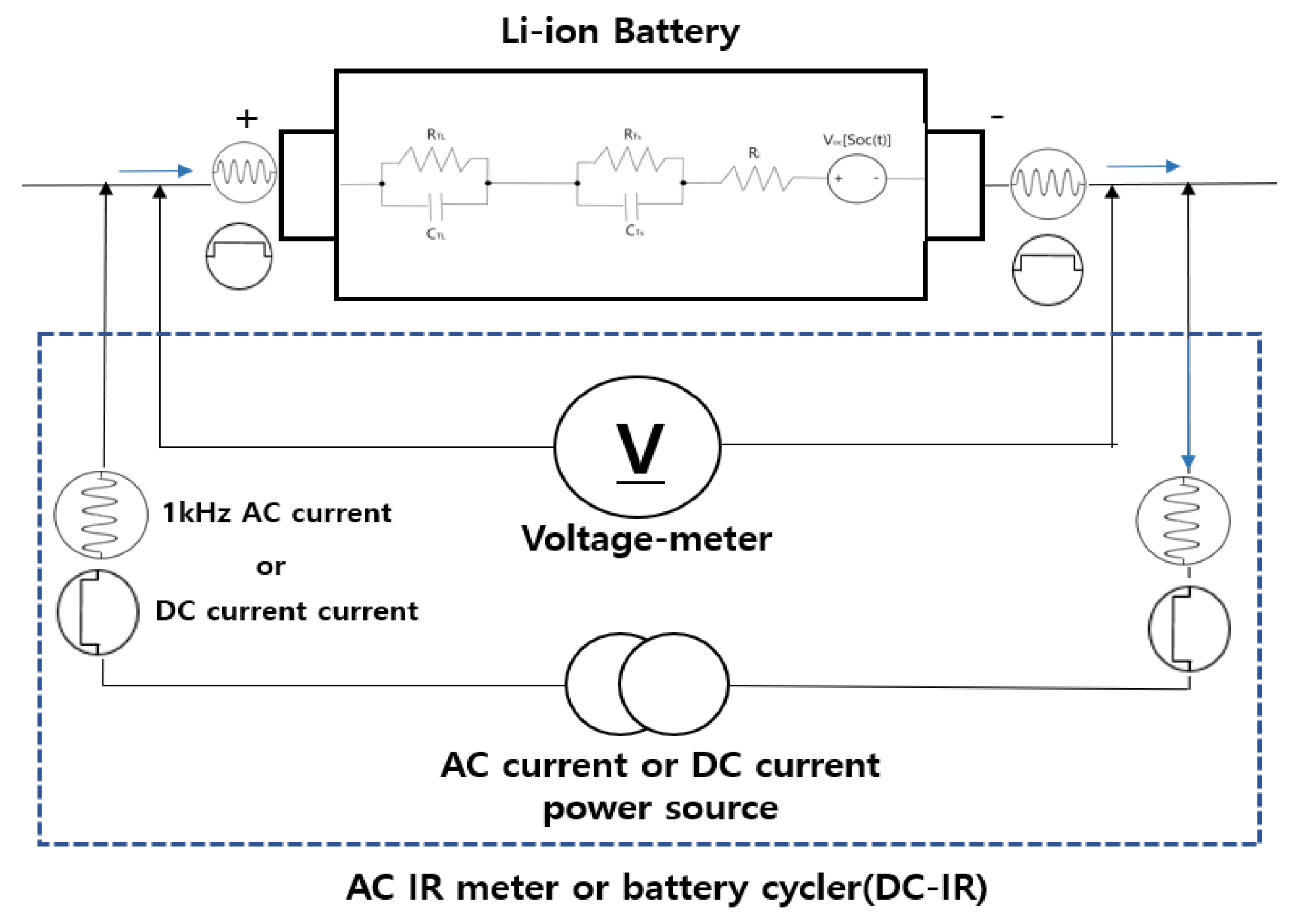
The AC IR method can be classified as an EIS method that measures while varying the frequency and a method that measures at a specific frequency. Both methods analyze the voltage response characteristics of the battery by passing alternating current through the battery cell. The main difference is that the AC IR method is measured at the frequency of 1 kHz, while the EIS method measures internal resistance over a wide range of frequencies by sweeping from several mHz to 30 kHz or higher [15]. In this frequency range, the total measurement time is 10 min or more. The EIS method takes more test time than the AC IR method. The EIS method shows the measurements results in the form of a Nyquist curve, which is hard to use to perform the judgement of pass or fail because it does not have a specific value. The EIS method is typically used to analyze the impedance spectrum of a lithium-ion cell. This paper adopts the AC IR method measuring at a frequency of 1 kHz for 1~5 s, which is presented in several international standards [6,7,8,9]. The AC IR method is a simple and rapid measurement which is used in the battery cell manufacturing process and in incoming and outgoing inspections. It is also applied to cells within the IEC 61960-3 standard for batteries used in portable devices and the IEC 62620 standard for industrial batteries, including ESSs. At a frequency of 1 kHz, the AC IR method reflects the resistance according to the movement of lithium ions in the electrolyte. It is used as an important test in the production process because it not only verifies that the electrolyte is properly injected but also measures the resistance of the connection. In this paper, an alternating current () with 1 kHz frequency is input to the battery based on the AC IR measurement method of IEC 62620 as shown in Figure 2, and then the internal resistance () is calculated by the measured voltage () as shown in Equation (1) [16]. The alternating current should be adjusted so that the peak voltage is maintained within 20 mV [8].
where is the 1 kHz root mean square (RMS) current, is the AC IR, and is the AC RMS voltage.
Since the AC IR measurement method has been mostly used for cells and small packs for portable small devices, the measurement method of high-voltage batteries in medium and large battery cells, modules, and packs for repurposing batteries is urgently required. The AC IR measurement method also has the advantage of measuring the reactive component since it applies a high-frequency AC source, so it can accurately measure the connection degradation of medium and large modules and pack batteries. On the other hand, the equivalent circuit model adopted in this paper is the Randles model, which represents the changing internal state of the battery with degradation as a combination of resistors and capacitors [17]. The AC IR method adopts a high frequency of 1 kHz to measure electrolyte resistance in the Randles model.
3.1.2. DC IR
The mechanism of DC IR measurement calculates the internal resistance based on the voltage variation with inputting DC for a constant time interval [18]. As shown in Figure 3, by discharging the battery with a constant current () for a short period of time, the voltage of and are measured with the increased discharge current (), and then the internal resistance () is calculated using Equation (2) [6,7,8,9].
where is the DC IR, is the measured voltage, and is the discharge current
In addition to the method of measuring internal resistance during discharging the battery as mentioned above, there is also a method of measuring internal resistance during charging [19]. The DC IR method is used to assess battery health, predict life span, and estimate system SOC, capacity, and more. Pulse current tests are typically performed for 1~30 s, and the measured DC internal resistance includes resistances inside the battery, such as ohmic polarization, electrochemical polarization, and concentration polarization. However, the DC IR method has the disadvantages of SOC change because the battery is partially charged and discharged by the DC during the internal resistance measurement and it causes differences in repeated measurements. In addition, a long test preparation time is required, such as preparing the charging and discharging equipment and fixing the current path. However, the DC IR measurement method has advantages over the AC IR measurement method in that it can be measured while supplying DC under the same conditions as actual applications, it can measure degradation characteristics according to high current in real operation, and in the case of large-capacity batteries connected to an inverter it can perform on-site evaluation without connecting a separate test device. However, although DC IR measurement methods have been applied for small, medium, and large cells and small packs, studies on the reliability of the measurements under operation conditions such as the SOC, SOH, and temperature are required in used batteries.
3.2. Internal Resistance Measurement Mechanism Considering Environmental Factors
In order to improve the accuracy and efficiency of the internal resistance measurement method, this paper proposes an evaluation method considering environmental parameters of the battery such as the SOC, degradation rate, operating temperature, and torque of the electrical connection.
Firstly, as shown in Figure 4, the open circuit voltage (OCV) of an NMC-type battery may be varied depending on the SOC, and this is due to ion relaxation between charge and discharge and the transition diffusion of active materials during charge and discharge. Depending on the characteristics of the battery, there is a section with a small slope at SOC 50% and a high slope at SOC 20% lower and 80% higher, which means relatively larger internal resistance.
Secondly, as degradation phenomena of batteries, the thickening of the solid electrolyte interphase (SEI) layer, reduction in lithium ions in the active material, and loss of active material occur in batteries [20]. The increased internal resistance of the battery cell by the SEI layer thickening and the loss of active material reduce the diffusion rate of solids. Therefore, in the case of used batteries, degradation of the batteries varies depending on the operational conditions of each vehicle, so it is necessary to check the state of the used batteries through internal resistance evaluation.
Thirdly, an ion’s electrochemical reaction velocity changes according to the temperature of the battery. As the temperature increases, the diffusion of reactive materials accelerates and then an ion’s conductivity increases, which allows electrical charges to move more easily and reduces the internal resistance of the battery. The conductors for electrical connections inside the battery pack and the metal conductors inside the battery cells are characterized by a resistivity coefficient that decreases with increasing temperature, as shown in Figure 5. The coefficient of resistivity is a temperature characteristic of the material and is expressed in Equation (3).
where is resistance, is the resistivity coefficient, is the length, and is the area.
Finally, battery packs are electrically connected by metal conductors between each module, and the torque between the bolts and nuts for connecting the battery may be loosened due to mechanical vibration or shock during the driving of an electric vehicle, so an internal resistance measurement method to consider the torque characteristics is strongly required. Therefore, the AC IR method, which can measure the reactance component, is considered more useful than DC IR, which only measures the resistance component.
4. Implementation of Internal Resistance Test Device for Medium and Large Batteries
4.1. Internal Resistance Test Device for Battery Cell
The configuration of the test device for measuring the internal resistance of medium and large battery cells is shown in Figure 6. The test device consists of an AC and DC power source section, a sensing section, and a lithium-ion battery cell, as shown in Figure 6, and measures the internal resistance due to voltage variation for a short period by supplying AC and DC to the positive and negative terminals of the battery cell. Here, the AC power source section supplies an AC with 1 kHz frequency to the battery according to the mechanism in Section 3.1.1, and the DC power source section performs charging and discharging at different c-rates according to the mechanism in Section 3.1.2. The sensing section also measures the charge and discharge currents and the voltage of the lithium-ion battery, which can be used to measure changes in internal resistance as the battery cell degrades. On the other hand, the internal resistance of a battery can be changed by various conditions; therefore, this paper evaluates the internal resistance according to operation conditions such as the SOC, SOH, and temperature to determine the performance and safety of battery cells.
4.2. Internal Resistance Test Device for Battery Pack
As shown in Figure 7, the internal resistance test device for medium and large battery packs is composed of an AC and DC power source section, a sensing section, and a battery section containing lithium-ion battery cells, fuses, relays, and a BMS. The device is configured to supply current to the positive and negative terminals connected externally to the battery pack to measure internal resistance with the voltage variation. In addition, unlike the battery cell test device, battery pack level internal resistance measurements can detect degradation of the battery cells as well as abnormality in the battery current path because the supplied current from the power source passes through connections, relays, and fuses in the battery pack. There are numerous junctions inside the battery pack for electrical connections, the defects of which can appear as internal resistance due to connection degradation. In addition, not only the resistance characteristics of battery cells but also connection points and other components can be affected by operation conditions such as temperature. Therefore, in this paper, the internal resistance of the battery pack is evaluated based on parameters such as the SOC, SOH, and temperature to assess the performance and safety of the battery pack.
5. Case Studies
5.1. Test Conditions
This paper presents the internal resistance characteristics of a battery by measuring the internal resistance under test scenarios with commercial NMC-type medium- and large-sized batteries. The SOC setting method for each test scenario is performed according to IEC 62660-1 [21], which involves charge, stabilization time, and discharge procedures. The SOC value for the internal resistance test is assumed as shown in Table 1 based on international standards. In other words, the SOC for AC IR measurements is assumed as 50%, specified in IEC 62620, the maximum and minimum values of 100% and 0% are assumed for the operation range, and a typical 25% is assumed for transportation and storage. The SOCs for the DC IR measurement are assumed as the minimum value of 20% and the maximum value of 80%, specified in UL 1974 and ISO 12405-4, and 50% specified in IEC 62620. In addition, the currents applied in the test are assumed to be 0.2C and 1.0C as specified by UL 1974, and safety conditions are set considering the upper and lower voltage limits.
On the other hand, for the internal resistance according to the SOH, it is measured after performing the capacity measurement procedure in IEC 62620. In addition, to measure the internal resistance according to temperature, the operation temperatures of EV batteries ranging from 0 °C to 50 °C are applied in increments of 10 °C. The torque value of the connection between modules is adjusted depending on the degradation situation in connections.
5.2. Characteristics of Internal Resistance Depending on SOC
The internal resistance characteristics of the batteries using the AC IR measurement method depending on the SOC are shown in Table 2. As a result of used batteries from EVs based on the 0% SOC as a reference, it is confirmed that the AC IR measurement tends to decrease as the SOC increases, but the decrease is around 3%, not as large as that of DC IR. In particular, it is found that the distribution degree of internal resistance for the AC IR measured at SOCs of 0% and 25% are both within 1.8%.
The internal resistance characteristics using the DC IR measurement method of the batteries depending on the SOC are shown in Table 3. Regarding the batteries for EVs on the basis of a reference value of a 20% SOC, the DC IR measurements at a 50% SOC show distribution degrees within 5% of the maximum value. On the contrary, in the case of SOCs of 20% and 80%, the battery has a higher DC IR than the case of an SOC of 50% due to the characteristics of lithium-ion batteries where an SOC of 50% is located in a flat region of the voltage–current discharge curve with a relatively small slope. Therefore, it is important to specify SOC conditions when measuring the internal resistance, as AC IR and DC IR measurements have large distribution degrees depending on the SOC.
5.3. Characteristics of Internal Resistance Depending on SOH
The internal resistance characteristics using the AC IR measurement method of the batteries depending on the SOH are shown in Figure 8. Regarding the batteries for EVs on the basis of reference value of a 100% SOH, it is found that the AC IR measurements tend to increase as the SOH decreases. It is confirmed by AC IR measurements that internal resistance increases as the battery cell degrades and the AC IR measurements increase by around 7% from the initial value according to the degradation progress.
On the other hand, the internal resistance characteristics using the DC IR measurement method of the batteries depending on the SOH are shown in Figure 9. Regarding the batteries for EVs on the basis of a reference value of a 100% SOH, it is found that the DC IR measurements tend to increase as the SOH decreases. The DC IR method has a greater effect on the SOH compared to the AC IR method because it reflects the pure ohmic resistance, electrolyte ionic resistance, and the charge transfer resistance caused by cell degradation. It is confirmed by DC IR measurements that the internal resistance increases as the battery cell degrades and the DC IR measurements increase by more than 50% from the initial value according to the degradation progress. Since the distribution degree of DC IR measurements is larger than the AC IR measurements depending on the SOH, it is known that the DC IR method is more effective in the diagnosis of battery cell degradation.
5.4. Characteristics of Internal Resistance Depending on Temperature Condition
The internal resistance characteristics using the AC IR measurement method of the batteries depending on the temperature condition are shown in Figure 10. Regarding the batteries for EVs on the basis of a room temperature reference value of 25 °C, it is confirmed that the AC IR measurements are saturated regardless of the temperature, and the internal resistance value decreases as the temperature increases. It is seen that the overall resistance decreases as the conductors inside the battery pack and the resistivity coefficient (ρ) of the battery cells become smaller while temperature increases. Therefore, it is found that the AC IR measurement method has a distribution degree of up to 6% from room temperature, indicating that the specified temperature conditions must be observed when measuring internal resistance.
On the other hand, the internal resistance characteristics using the DC IR measurement method of the batteries depending on the temperature are shown in Figure 11. Regarding the batteries for EVs on the basis of a reference value of 0 °C, it is found that the DC IR measurements tend to decrease as the temperature increases. There is a distribution degree of up to 70% of each temperature for the DC IR measurements since there are not only the factors of conductors inside the battery pack and the resistivity of the battery cells in the same way as in AC IR, but also a greater influence of battery chemical characteristics which are charged and discharged by the current in the DC IR test. Therefore, it is found that the distribution degree of the DC IR measurements is up to 70% from room temperature, which means that the temperature conditions during the test must be observed more strictly than in the AC IR test. Even though the AC IR method is less affected by temperature than the DC IR method, its measurements can be changed according to the cell temperature. Therefore, the ambient temperature has to be maintained constantly, and the battery pack needs to be soaked for a long time because it takes time to fully saturate the inside of the pack.
5.5. Characteristics of Internal Resistance Depending on Connection Degradation
Table 4 shows the internal resistance characteristics of the AC and DC IR measurement methods considering the degradation of the connections between modules as the torque value to assume connection degradation. The procedure for the measurement of connection degradation is as follows. First, check the battery pack condition and then measure the internal resistance with the AC IR and DC IR methods. Second, increase the resistance of the electrical connection to simulate the degradation of connections. Third, evaluate the internal resistance characteristics for the degradation of connections. Regarding the degradation of connections for EVs on the basis of reference values of normal operation, the DC IR measurements show an increase of less than 1% regardless of the SOC, while the AC IR measurements show an increase of up to 319%. The connection degradation is affected by the capacitance component, which is produced as the torque value decreases, and the connections of the pack are more affected than the battery of the pack. Therefore, it can be seen that the AC IR measurement is more effective than DC IR in the diagnosis of degradation at the connection between battery modules.
6. Conclusions
This paper performs internal resistance measurements for used batteries under various test conditions such as the SOC, SOH, temperature, and connection degradation for NMC-type lithium-ion batteries, which are the most widely used medium- and large-sized batteries in Korea. The main results are summarized as follows:
(1) The AC IR and DC IR measurement methods according to the SOC test conditions show distribution degrees of up to 3% and 5%, respectively. Therefore, there is no significant difference between AC and DC IR, but it is confirmed that it is desirable to determine a specific SOC range when measuring internal resistance.
(2) Since the distribution degrees of the AC IR and DC IR measurement methods under the SOH test conditions are about 7% and 50%, it is found that DC IR measurement method is more effective in the diagnosis of battery cell degradation. It is expected that the increase in internal resistance according to the battery degradation is caused by the chemical characteristics of batteries, which is significantly reflected in the voltage variation with the actual discharge current.
(3) As the distribution degrees of the AC IR and DC IR measurement methods according to the temperature test conditions are about 6% and 70%, it is found that the DC IR measurement method needs to specify temperature conditions more strictly than the AC IR measurement method. The DC IR method effectively evaluates the battery chemical characteristics for the increase in internal resistance due to the resistivity coefficient of the conductors of battery cells and battery packs, which is reflected in the voltage variation with the actual discharge current.
(4) The DC IR measurements for the degraded connection condition show an increase of less than 1% regardless of the SOC, while the AC IR measurements show an increase of up to 319%. The AC IR method, which can measure the reactance component, is considered as more useful than DC IR, which only measures the resistance component.
(5) Based on the above results, it is found that the temperature and SOC conditions should be observed when measuring the internal resistance for battery repurposing. The DC IR measurement method is suitable for measuring the degradation of the cells, and the AC IR measurement method is suitable for measuring the degradation of the connections.
This paper deals with operating environment conditions such as the temperature, SOC, and SOH during the inspection of the internal resistance test method, which is one of the inspection methods used to diagnose the performance and safety of used batteries. However, various scenario-based scientific and systematic studies will be required for accurate diagnoses in the field of used batteries. In addition, based on further evaluation methods for different battery models, the characteristics of each model will be studied in the future.
Author Contributions
Methodology, M.-G.L.; Validation, M.-G.L., N.-H.K., J.-M.K. and J.S.; Formal analysis, M.-G.L. and J.-B.J.; Resources, M.-G.L. and J.-B.J.; Data curation, J.-B.J.; Writing—original draft, M.-G.L.; Writing—review & editing, J.-B.J. and D.-S.R.; Visualization, J.-B.J.; Supervision, D.-S.R.; Project administration, D.-S.R. All authors have read and agreed to the published version of the manuscript.
Funding
This work was supported by the “Development of ship ESS safety evaluation system and establishment of test certification base” of the Korea Institute of Energy Technology Evaluation and Planning (KETEP) which granted financial resources from the Ministry of Trade, Industry, and Energy, Republic of Korea (No. 20215410100010). This research was also supported by a Korea Institute of Energy Technology Evaluation and Planning (KETEP) grant funded by the Korean Government (MOTIE) (No. 20224000000160, DC Grid Energy Innovation Research Center).
Conflicts of Interest
The authors declare no conflict of interest.
References
- Jung, J.B.; Lim, M.G.; Kim, J.Y.; Rho, D.S. Characteristics of External Short-Circuit in Li-ion Battery Considering Operation and Environment Factors. J. Korea Acad.-Ind. Coop. Soc. 2021, 22, 663–672. [Google Scholar] [CrossRef]
- Kim, J.M.; Tae, D.H.; Lee, I.M.; Lim, G.P.; Rho, D.S. A Study on Modeling of Leakage Current in ESS Using PSCAD/EMTDC. Korea Acad. Ind. Coop. Soc. 2021, 22, 810–818. [Google Scholar] [CrossRef]
- Choi, S.M.; Jian, S.; Kim, M.Y.; Son, J.H.; Rho, D.S. Operation Algorithm for Protection Cooperation Device in High Voltage Customer with ESS for Demand Management. J. Korea Acad.-Ind. Coop. Soc. 2021, 22, 437–446. [Google Scholar] [CrossRef]
- Ryll, K.; Hoffmann, L.; Landrath, O.; Lienesch, F.; Kurrat, M. Key Figure Based Incoming Inspection of Lithium-Ion Battery Cells. Batteries 2021, 7, 9. [Google Scholar] [CrossRef]
- Fly, A.; Wimarshana, B.; Bin-Mat-Arishad, I.; Sarmiento-Carnevali, M. Temperature dependency of diagnostic methods in lithium-ion batteries. J. Energy Storage 2022, 52, 104721. [Google Scholar] [CrossRef]
- IEC 61960-3; Secondary Cells and Batteries Containing Alkaline or other Non-Acid Electrolytes—Secondary Lithium Cells and Batteries for Portable Applications—Part 3: Prismatic and Cylindrical Lithium Secondary Cells and Batteries made from Them. International Electrotechnical Commission: Geneva, Switzerland, 2017.
- IEC 62620; Secondary Cells and Batteries Containing Alkaline or other Non-Acid Electrolytes—Secondary Lithium Cells and Batteries for Use in Industrial Applications. International Electrotechnical Commission: Geneva, Switzerland, 2023.
- ISO 12405-4; Electrically Propelled Road Vehicles—Test Specification for Lithium-Ion Traction Battery Packs and Systems—Part 4: Performance Testing. ISO: Geneva, Switzerland, 2018.
- UL 1974; The Standard for Evaluation for Repurposing Batteries. UL Standard: Northbrook, IL, USA, 2018.
- Yangmeng, L.; Ziwei, Z.H.; Baoquan, L.I. A calculation method for estimating internal resistance of battery online. Energy Storage Sci. Technol. 2019, 8, 264–268. [Google Scholar]
- IEC 63330; Requirements for Reuse of Secondary Batteries. International Electrotechnical Commission: Geneva, Switzerland, 2023.
- Ma, S.; Jiang, M.; Tao, P.; Song, C.; Wu, J.; Deng, T.; Shang, W. Temperature effect and thermal impact in lithium-ion batteries: A review. Prog. Nat. Sci. Mater. Int. 2018, 28, 653–666. [Google Scholar] [CrossRef]
- Mikolajczak, C.; Kahn, M.; White, K.; Long, R.T. Lithium-Ion Batteries Hazard and Use Assessment; The Fire Protection Research Foundation: Quincy, MA, USA; Springer: Berlin/Heidelberg, Germany, 2011. [Google Scholar]
- Gao, Z.; Zhang, X.; Xiao, Y.; Gao, H.; Wang, H.; Piao, C. Influence of Low-Temperature Charge on the Mechanical Integrity Behavior of 18650 Lithium-Ion Battery Cells Subject to Lateral Compression. Energies 2019, 12, 797. [Google Scholar] [CrossRef] [Green Version]
- Magar, H.S.; Hassan, R.Y.A.; Mulchandani, A. Electrochemical Impedance Spectroscopy (EIS): Principles, Construction, and Biosensing Applications. Sensors 2021, 21, 6578. [Google Scholar] [CrossRef]
- Mori, T. Advanced Technologies for Impedance-based Performance Estimation and Deterioration Diagnosis of Lithium-ion batteries. Kogyo Zairyo 2021, 69, 30–35. [Google Scholar]
- Kampouris, D.K.; Ji, X.; Randviir, E.P.; Banks, C.E. A new approach for the improved interpretation of capacitance measurements for materials utilised in energy storage. Rsc Adv. 2015, 5, 12782–12791. [Google Scholar] [CrossRef] [Green Version]
- Barai, A.; Uddin, K.; Widanage, W.D.; McGordon, A.; Jennings, P. A study of the influence of measurement timescale on internal resistance characterisation methodologies for lithium-ion cells. Sci. Rep. 2018, 8, 21. [Google Scholar] [CrossRef] [Green Version]
- Sharma, U.; Jain, S.; Tripathi, S.; Sharma, V. Novel Pulse Power Estimation Technique for Li—Ion Battery Using DCIR and SOC Relationship. EasyChair, 5 March 2020. Available online: https://easychair.org/publications/preprint/gPp1 (accessed on 4 July 2023).
- Wang, A.; Kadam, S.; Li, H.; Shi, S.; Qi, Y. Review on modeling of the anode solid electrolyte interphase (SEI) for lithium-ion batteries. npj Comput. Mater. 2018, 4, 15. [Google Scholar] [CrossRef] [Green Version]
- IEC 62660-1; Secondary Lithium-Ion Cells for the Propulsion of Electric Road Vehicles—Part 1: Performance Testing. International Electrotechnical Commission: Geneva, Switzerland, 2018.
Figure 1.
Types of degradation for middle- and large-sized batteries.

Figure 2.
Measurement method for AC IR of battery.

Figure 3.
Measurement method for DC IR.

Figure 4.
OCV curve according to SOC.

Figure 5.
Resistivity coefficient of conductor according to temperature.

Figure 6.
Configuration of measurement for cell internal resistance.

Figure 7.
Configuration of measurement for pack internal resistance.

Figure 8.
AC IR characteristics according to SOH conditions.

Figure 9.
DC IR characteristics according to SOH conditions.

Figure 10.
AC IR characteristics with ambient temperature conditions.

Figure 11.
DC IR characteristics with ambient temperature conditions.


Table 1.
SOC test condition for internal resistance with related standards.
| Standards | SOC Conditions for AC IR | SOC Conditions for DC IR |
|---|---|---|
| UL 1974 | - | 20%, high SOC |
| ISO 12405-4 | - | 20~80% |
| IEC 62620 | (50 ± 10)% | (50 ± 10)% |
| Test SOC | 0/25/50/100% | 20/50/80% |
Table 2.
AC IR characteristics according to SOC conditions.
| SOC (%) | ||||
|---|---|---|---|---|
| Sample | 0% | 25% | 50% | 100% |
| No.1 | 100.00 | 98.21 | 97.51 | 96.58 |
| No.2 | 100.00 | 98.77 | 98.21 | 96.98 |
| No.3 | 100.00 | 99.58 | 98.10 | 98.03 |
Table 3.
DC IR characteristics according to SOC conditions.
| SOC (%) | |||
|---|---|---|---|
| Sample | 20% | 50% | 80% |
| No.1 | 100.00 | 94.94 | 98.64 |
| No.2 | 100.00 | 95.73 | 99.71 |
| No.3 | 100.00 | 98.28 | 102.02 |
Table 4.
Temperature of charge preprocess in standards applied to small- and large-sized batteries.
| Items | SOC | Normal Status IR (%) | Connection Degradation IR (%) | Rate of Increase |
|---|---|---|---|---|
| AC IR | 30% | 100.00 | 217.62 | 117.62 |
| 90% | 100.00 | 419.68 | 319.68 | |
| DC IR | 30% | 100.00 | 100.89 | 0.89 |
| 90% | 100.00 | 100.68 | 0.68 |
Disclaimer/Publisher’s Note: The statements, opinions and data contained in all publications are solely those of the individual author(s) and contributor(s) and not of MDPI and/or the editor(s). MDPI and/or the editor(s) disclaim responsibility for any injury to people or property resulting from any ideas, methods, instructions or products referred to in the content. |
© 2023 by the authors. Licensee MDPI, Basel, Switzerland. This article is an open access article distributed under the terms and conditions of the Creative Commons Attribution (CC BY) license (https://creativecommons.org/licenses/by/4.0/).
Share and Cite
MDPI and ACS Style
Lim, M.-G.; Jung, J.-B.; Kim, N.-H.; Kim, J.-M.; Shen, J.; Rho, D.-S. Evaluation Method of Internal Resistance for Repurposing Using Middle and Large-Sized Batteries. Energies 2023, 16, 5652. https://doi.org/10.3390/en16155652
AMA Style
Lim M-G, Jung J-B, Kim N-H, Kim J-M, Shen J, Rho D-S. Evaluation Method of Internal Resistance for Repurposing Using Middle and Large-Sized Batteries. Energies. 2023; 16(15):5652. https://doi.org/10.3390/en16155652
Chicago/Turabian StyleLim, Min-Gyu, Jae-Beom Jung, Nam-Hyun Kim, Ji-Myung Kim, Jian Shen, and Dae-Seok Rho. 2023. "Evaluation Method of Internal Resistance for Repurposing Using Middle and Large-Sized Batteries" Energies 16, no. 15: 5652. https://doi.org/10.3390/en16155652
Note that from the first issue of 2016, this journal uses article numbers instead of page numbers. See further details here.